Fenix+ 3 Update v3.6.1
For this release, we have expanded available settings for the **Ventilation** and **Fire Source** elements. You can now set changing air flow rates for different vents in the project, set how the fire spreads on the surface and what ignition formula it follows - quadratic, linear or custom.
We have also added several quality of life changes:
The “IFC 2x3” format is now supported for importing topology.
Improved the quality of people's navigation during evacuation simulations — some edge cases will no longer lead to occupants “Looping.”
Now, you can view the intermediate results of the simulation if it ended in a “Looping” status.
Additional Fire Source Settings
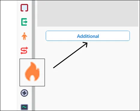
To access the detailed settings for the Fire Source, select the object placed in the scenario, go to the right side of the screen, to object parameters, and click the Additional button.
The additional properties window displays fire source properties determined by it's size and the material it is placed on, and some other options that you can change yourself. You can select the ignition mode: fire could spread from the center, or instantly, across the entire surface of the body. You can also select the fire spread law: quadratic, linear, and arbitrary. Each law could be applied to three values: S (burn area, in m²), Ψ (burn rate, in kg/s), Q (power, in kW).
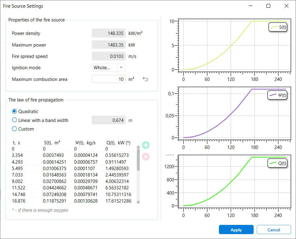
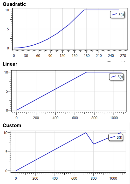
Switching the law parameter will change how the graphs on the right side of the window will look, showing, approximately, how the fire dynamics will develop over time:
The custom option allows you set the values to your preferences for each moment of ignition time. To do this, add, delete or edit a timestamp line in the table under the "custom" option — related quantities will be automatically recalculated.
Fore more info on the fire source properties, see our userguide.
Additional Ventilation Parameters
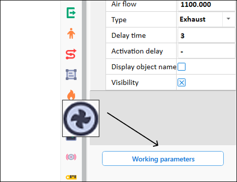
To access the additional Ventilation settings, select the vent placed in the scenario (any type), go to object parameters and click the Working Settings button.
Here, you can set variable working mode for the vent. For example, model “acceleration” or “attenuation”. To do this, add a new timestamp line in the table under Operating time after switch on subsection, and the ventilation will gradually reach the specified air flow rate at the specified time. This will show on the graph on the right side of the window, which would update with the table data.
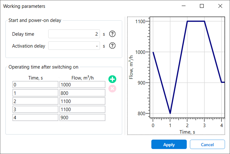
You can add or remove a time stamp by clicking on the green plus or red cross buttons. You can place place the timestamps in any order — after simulation starts, the vents will read them in chronological order.
And for more info on various types of ventilation in Fenix+, see the page in our userguide.